S3020 Build and Review (by Dr. Ralph Okon, AKA PowerCroco)
Dr. Ralph Okon 03052008
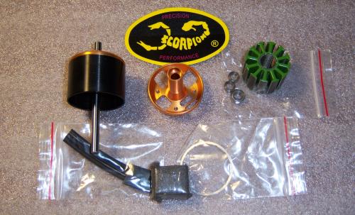
This is the scorpion 3020 kit as I got it.
Its all in what you need to build the motor without magnet glue and magnet wire.
The parts are made in very good quality - just as seen into the 3014 kit!
I decided to built this motor "very custimized" - I wanted to know, what is reachable with these fine parts.
At first I decided to use only 10 magnetpoles to reach the targeted higher kv. To realise this, I ordered 10 of the "replacement" magnets thougt for the 4020 motor. These magnets are broader, a bit thicker and of course stronger than the original ones. So I got an optimal coverage of about 75% and a reduced airgap. May be the backiron is a bit small for this configuration but imho strong enough.
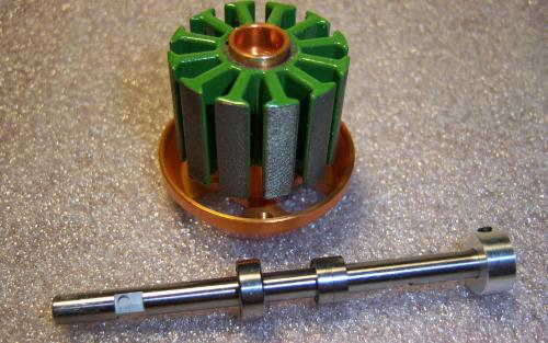
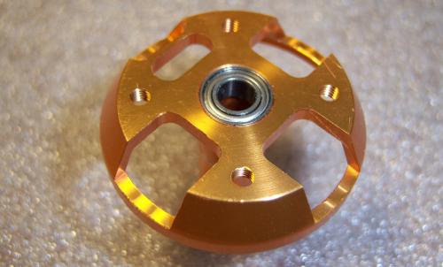
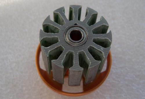
The statorpackage on the holder and the hardened 5mm shaft with the bearings and fine grinded flattenings for good setting for the holding srews.
Because of I personally hate the way to bear a shaft with 3 bearings (and 2 very smalls) I decided to replace them.
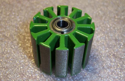
The bigger bearing - thought for the statorholder side - fits direct into the hole of the statorpackage. It's a MR 105 ZZ bearing and you can get it into the shops as replacement too.
The other MR 105 ZZ bearing I built in into the statorholder.
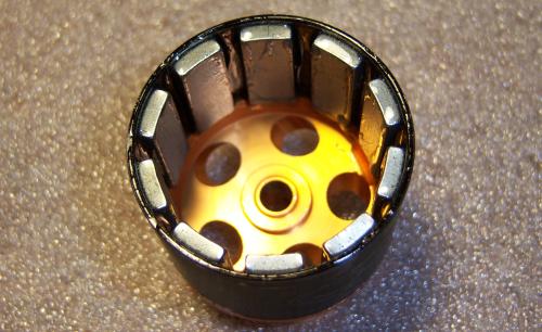
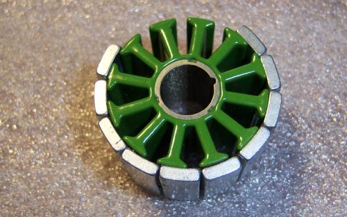
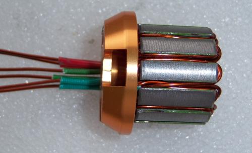
The magnets are places into the backiron and glued with a 2-componet gluing system.
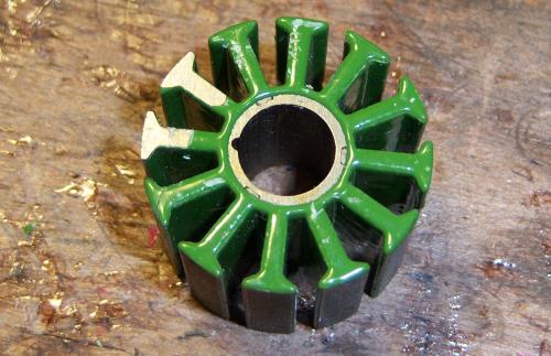
I was so stupid, to let roll my statorpackage from my table.....
The fine 0,2mm plates wre okay, but the insulation was damaged on 2 teeth.
My way to fix such problems is described here.
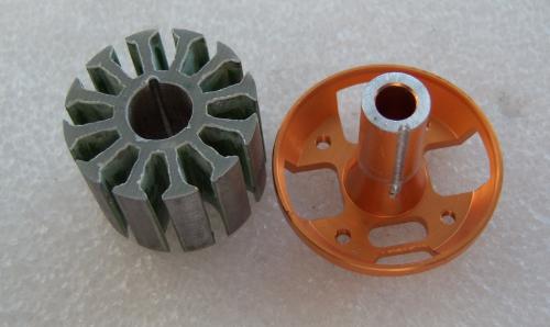
The fixed package and the customized statorholder.
The sets for the 2 small bearings are completly removed.
I put the package on the holder and bored the screw safety hole into the statorholder.
The first halfhole is just stamped into the plates and so you only have to bore its aluminium side.
A test:
The big bearing fits accurate into the statorhole.
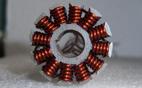
I winded 12N10P distributed scheme (AabBCcaABbcC) in small groups and used "Zick-Zack-Mode" for the 6. turn.
Here the first 5 turns.
The used magnetwire has 1,12mm diameter.
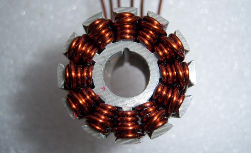
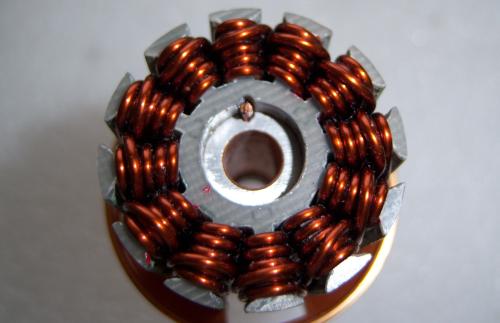
View of the completed winding from the front side.
You can see the 6. zick-zack turn.
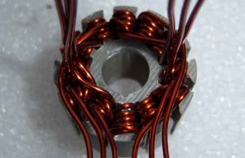
Here is the bottom side.
All wire ends are just prepared for the correct switching in the group parallel WYE scheme.
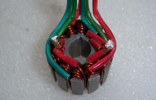
The star-points are solderes and all wires are insulated.
The completed statorpackage on the holder.
For srcew-prevention I glued a rest of magnet-wire into the boring.
Then I put the bearing on its place and glued all.
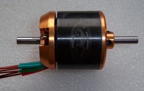
The completed motor weights 172g.
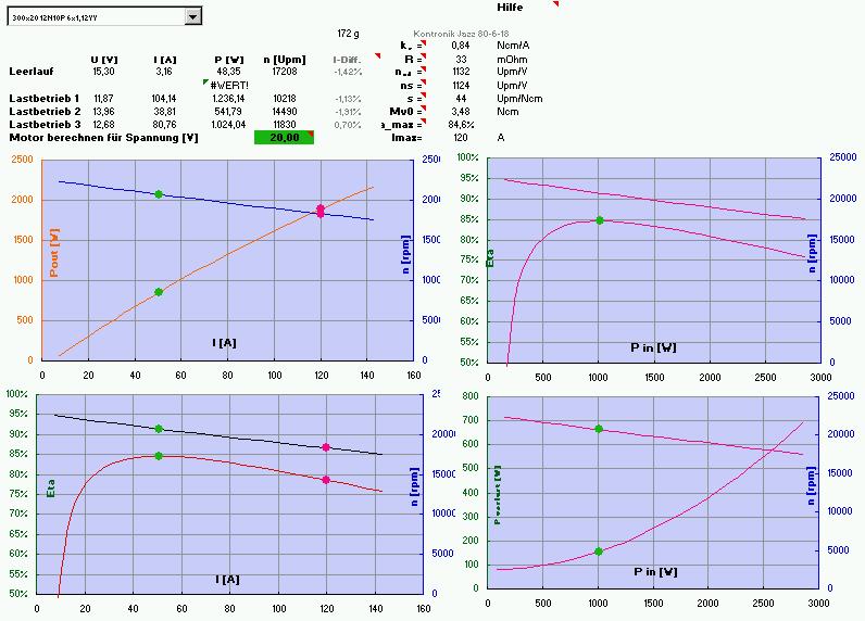
My conclusion:
- I got a real powerhouse- up to 2000W with a 172g motor.
- The kv messured with kontronik JAZZ ESC is 1130/V.
- Max efficiency for 6s Lithiumbatteries is about 84% and the usable >80% eta-range reaches from 25 to 100A !!!
The 100A is only for short (10sec) for saiulplane climbing p.e. - The only 37mm diameter fits good into smaller bodys.
- Using 5s is an aeronaut 10"x8" prop with 42mm middlepart you will get 15.000rpm = 50m/s pitchspeed.
With 100Amps you will get 4kg thrust for short times.
So I got, what I was searching for - a high efficienthotliner direct drive.